
Towards Visually-Guided Neuromorphic Robots
| Home |
| Overview |
| News |
| Hardware |
| Software |
| Gallery |
| Downloads |
| Team |
| Publications |
| Sponsors |
| Links |

Beobot Prototyping
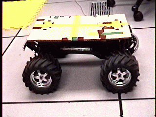 | The base RC-car mobile platform, prepared for our first video shoot, in which we simply mounted a camcorder on it and drove it manually. |
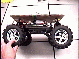 | The car runs at 25 MPH for about 20 minutes on a standard set of two 7.2V battery packs. We will equip the beobots with four packs and many additional Li-Ion camcorder batteries to power the on-board quad-CPU Beowulf. Ruchi has found cool battery packs and DC/DC converter chips which we are experimenting with. |
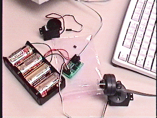 | Controlling the servomechanisms (which allow the robot to turn, accelerate, brake and switch between first and second gear) is working using a serial-to-servo converter and some software which Jen developed. Jen is now putting together a servo-based pan/tilt camera mount for the beobots. |
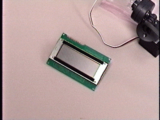 | Software to control the diagnostic LCD screen from a standard PC serial port is almost ready, from Jen and Paul. |
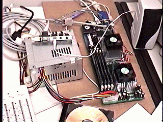 | The dual-CPU embedded motherboards (Rocky-3742EVFG, purchased from www.histar.com.tw) are working great. Eric installed Linux Mandrake 8.1 on a 256MB CompactFlash disk, and it was a breeze. The Gigabit Ethernet chip (which will link both boards in each beobot) was not automatically recognized during installation, but a kernel module is available for it, so it was trivial to configure. The default kernel did not include support for 1GB of memory, so we are cooking up a custom kernel with all the drivers required for the board. Video, sound, ieee1394, serial, parallel, etc are all working great under Linux. |
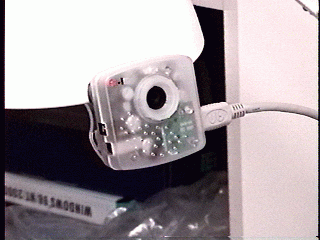 | We just wrote a high-level driver for these cool firewire (IEEE-1394) cameras. Each Beobot will have two such cameras, mounted on a pan/tilt head composed of two servomechanisms. |
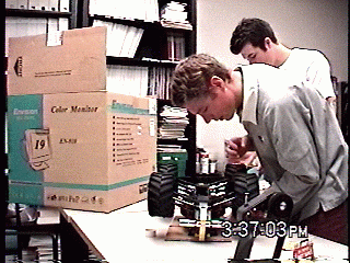 | Eric and Tony finish to prepare the robot for its first trip outdoors (under human control). Check it out here (8.5 MB MPEG movie, 30 fps). In this movie sequence, the attention model has its internal memory (inhibition of return) turned on, so, once it looks at any given object, it will not come back to it for a few seconds. In this respect, the attentional fixations shown in this movie differ from ours, as we tend to continuously fixate one interesting object when we find one that is relevant to our current task. Note how the model does find most interesting objects in the scene (hands, people, trees, pillars) though it only very briefly attends to each one. The autonomous beobots will use a combination of our attention model (to find possible obstacles and landmarks), a navigation system based on a rapid computation of the gist of the scene (where the road is, where the sky is, etc), and localized object recognition linked to the attention model, so that we can identify the targets being attended to. |
 | Nathan completed soldering together a prototype of our infernal power conversion system, which delivers up to 34A @ 5V to the CPU boards from batteries. Looks like we can power all four CPUs for slightly over an hour from 8 standard R/C battery packs. Great! |
 | Mounting the CPU boards onto the car chassis was challenging because the CPU boards have no mounting holes pre-drilled in them, and component density is so high that there is absolutely no room to drill anywhere on the boards. April found a great way of solving thie problem: the CPU boards rest on a rubber mat in which appropriate cut-outs have been laser-cut to accommodate for the various components soldered on the back side of the CPU boards. The rubber mat rests on a solid piece of laser-cut clear acrylic, the base board. Finally, a piece of thin laser-cut acrylic fits tightly around the CPU boards so that they cannot shift. The CPU boards are then maintained in place by many screws just adjacent to the CPU boards, so that the screw heads hold the boards without requiring any drilling into the boards. Click here for a larger image. |
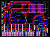 | The final version of our infernal power conversion system is ready for fabrication. The schematic diagram and printed circuit board layout were done using the freeware version of Eagle PCB software from Cadsoft. The circuit just fits within the 3x4in maximum board size available in the freeware vesion of Eagle PCB. Thank you Cadsoft! |
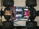 | Daesu completed a simple circuit (shown in front of the two motors) that allows us to switch between PC-controlled and radio-controlled by flipping a switch on the radio controller. This will allow us to easily take over the control of the robot in case of bug in our vision algorithms. |
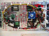 | The main platform, shown here from below, is ready to go. On the left, the mini-SSC interfaces the PCs to the car's servomechanism. On the right, the fan-cooled power conversion module delivers power to the CPUs from camcorder battery packs. |
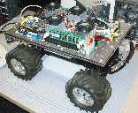 | The first prototype is basically ready and working; the last few components missing on this picture are the batteries, the protective shell, and the pan/tilt camera mounts. |
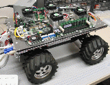 | Hook it up, install Linux Mandrake 8.2 on the flash drives, and off you go! |
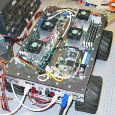 | This laser-cut control panel at the back of the robot was a real pain to assemble, because we had to cut and solder a zillion custom cables. But it is really useful to connect the beobot to a monitor, keyboard, mouse, GPS, speakers and microphone, various USB devices, etc. |