Table of Contents
In this section we are going to describe our decision process of how to go about supplying power to the motors and computers. The objective is to provide clean and fail-save power. The power to motors itself does not need to be filtered, but the power to the computer system must be.
Below, we specify the battery source (dictated by the wheelchair although can be easily replaced by other options), power requirements, the different options of implementing the power board, and our final decision. We also list the cables that we have to make to complete the circuit.
Battery
- Two 12V 35AH Sealed Lead Acid (SLA) batteries. SLA's are sturdy, cheap, and heavy. But, we have plenty of torque.
- Connected in series to produce 24V.
- Battery charging provided by the wheelchair.
Power Requirement
For a ETX-Express-MC 2.2GHz (T7500): 32 - 40A
- Each 35W typical 60W maximum.
- 3.3V: very little Amperage for the clock
- 5V: trickle: ~.5A
- 12V. profile: (Max + memory)*120% = 4 - 5Amp
- Total: 8 x 60W = 480W
Motors: 5A, Peripheral boards <1A
Power Supply System
We either build our own Power Supply Unit (PSU) or buy one off-the-shelf/online.
Building our own power board:
- Pro: Can build custom power profile (3.3VCC, 5VCC, 12VCC).
- PRO: Less cabling problem.
- CON: Longer prototyping cycle
- Con: No power protection management, no over discharge protection. no over peak protection.
- Price is probably about the same
Industry level power management system:
- Pro: fully engineered and tested
- Con: limited 12V Current (typically maximum of 12A)
- Con: Have to accommodate shape/size of the module
- Con: What do we do with the other inputs (-5VCC, -12VCC)? If they only supply small amount of current, it's ok to sacrifice them.
To speed up development time and be on the safe side (no blown board), we opt for buying the Pico ATX modules, from MiniBox.
Other manufacturers we considered:
- Congatec Smart Battery Management add-on module (SBM2). Ask for a schematic if ask for building our own.
Board Layout and Power Placement
The power supplied from the batteries is routed through the KVM board before arriving at the PICO ATX baseboards. Here, we try our best to keep the power rails as far away from noise sensitive high speed signals as possible. In addition, because we are dealing with high currents, we also lay thick traces to avoid overheating and power failures.
In the baseboard we utilize a power plane that includes power rails of 3.3V, 5V, 12V and 24V. There is also a separate ground plane.
Cables
For cable choices, we make sure that the cable have enough gauge to transfer the necessary currents. We also find that the flexible, silicon cable (whenever available) is an excellent option.
We can start following the power traces from its source the batteries. The batteries is first put in series before going into the case through a panel mount connector to the robot body. Most of the cabling in this section is provided by the Liberty 312 wheelchair (the platform provide a few fuses along the way). However for the end-cable, leading up to the panel-mount connector, we soldered in an 8AWG cable. We connect the battery system cable to the Amphenol 69 A panel mount connector using the 2 8AWG cables (4 total) for each power and ground. We also connect the 2 ends to the wall charger module (cable provided by the wheelchair).
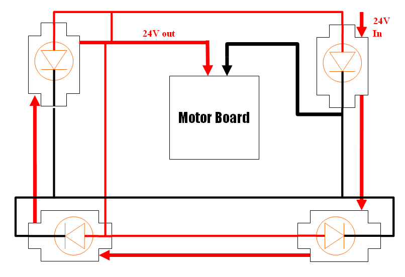
On the other side of the panel mount connector, the power is split to two sub-systems: computers (KVM, then to Base boards) and the motors (Killswitch → Motor Drivers → Motors).
We also have much lower power requirements from KVM to 3 peripheral boards: cooling board, sensor board, and motor board.
Computer Power
only 1 cable from the panel-mount Amphenol connector to the KVM board.
Case to KVM Board
We use 8AWG cable with an Amphenol Board connector.
Motor Power
There are a few cables that we need to put together:
Case to Killswitch Circuitry
We use 14AWG cable with a 40A fuse in between.
Killswitch Circuitry
The motor power goes 4 killswitches in the following order:
- Back left
- Front left
- Front right
- Back right
The cable is then connected to the motor driver.
There are also cables for killswitch lights that are wired in parallel, powered from the last last kill switch.
Motor Driver to Panel Mount output
Panel Mount to Motors' Power and Encoder
The cable is a bit complicated because there are 2 motors that needs to be connected. At the 19A 12pos Amphenol panel mount connector, we have 3 cables that meet up.
The first one is a 4 core 14AWG power cable to power both motors:
- Pin J: Red cable: R+
- Pin K: White cable: R-
- Pin L: Green cable: L+
- Pin M: Black cable: L-
The power connection on the motor side is provided by the wheelchair.
The second cable is for the encoder for the Left motor:
- Pin B: Red cable: VCC
- Pin A: White cable: D-
- Pin H: Green cable: D+
- Pin G: Black cable: GND
The data connection on the encoder side uses regular (cheap) circular connector.
The third cable is for the encoder for the Right motor:
- Pin C: Red cable: VCC
- Pin D: White cable: D-
- Pin E: Green cable: D+
- Pin F: Black cable: GND
The data connection on the encoder side uses regular (cheap) circular connector.
Peripheral Power
We use ATX power cables to connect power from from the KVM board to three peripheral boards: cooling board, motor board, and sensor board.
