Table of Contents
These are the sensors that are furnished in Beobot2.0:
Cameras
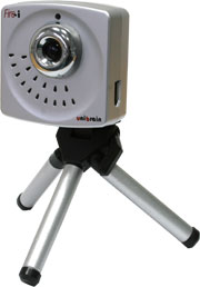
Since we are primarily a vision robotics research group, selection of a camera (and the corresponding lens) is very critical. In addition, our system is also trying to emulate human vision. Thus, we also have to keep in mind what kind of stimulus is available to human vision system. The problem that we encounter is that a single regular camera may not be enough: 60 degree horizontal field of view, and for our 1/4” CCD camera 117cm above the ground (current Beobot2.0 configuration), cannot see the view below, i.e. what's on the ground, 4 feet and closer.
FIXXX: field of view of a single camera vs whole half hemispheric view
Just as a comparison, humans use 2 cameras (eye) with 120 degree visibility that overlaps in the middle 60 degrees. Humans also have problems seeing their feet. However, there is also temporal context (short term memory) that comes into play with the ability to move their eyes as well as bodies.
FIXXX: picture of human eyes setup
Factors
The factors to consider are listed below. Here, we believe, the most important one is the effective views that can be processed:
- View: pertains to what the robot can see from the camera at any one time.
- Resolution: in order to recognize an object in the image, we need enough details to make it up
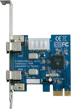
- Latency: pertains to the time delay between when the picture is snapped and the time the image is available to be processed. We find that Firewire cameras, interfaced through a Firewire - PCI Express card (purchased from UniBrain) provides us the lowest latency.
- High dynamic range
- Auto white balance gain control.
Tasks
We also have think about what kind of tasks that we would like to give the robot:
- Object/landmark recognition. This requires rectified images so that the lines are straight.
- road recognition. The camera needs to look down low enough to see the ground.
- Gist or general scene recognition which requires a wider view, preferably 180 degrees.
Hardware Features
There are many hardware options that are available. Here the parts that can be modified are:
- Cameras: dictates latency, resolution, gain control, etc. Also make sure the available corresponding lens options include the ones that fulfill our design.
- lens: By using wider (120/180 degrees) or omni-directional lens (hemisphere), the robot can observe more of its surrounding views.
   * Distorted images; have to consider cost of image rectification processing or just deal with it.
   * Lenses can be quite costly.
- number of cameras: by simultaneously taking pictures from multiple angles, we can provide the robot with wider views. The setup can be just 2 cameras, or may requires a rig.
   * Synchronization using cable locking.
   * Undistorted images.
   * Multiple cameras are somewhat cheaper than buying specialized lens.
   * Need to consider network throughput.
   * Also, need to combine the individual image processes.
   * Still needs to expand the vertical views (to see the road).
- motorized pan/tilt: for example, servo controllers for pan-tilt control: lyxmotion. Orbit is also another option.
   * Need Pan/tilt control algorithm
   * Small view at one time: need to stitch images from different time steps.
   * Cheap options, cheaper than buying expensive lenses or multiple cameras.
   * Swiveling may induce blurring in fast movements.
Options
- Single camera with 120 degree wide angle lens or 180 degree or omni-directional fisheye lens.
- Pair of 120 degree wide angle cameras.
- 5 cameras in circular configuration spaced every 45 degrees.
- Pan/tilt cameras.
- 3D cameras about to come out around Summer 2010.
Related Notes:
- Multiple cameras is not a problem if each camera is processed locally in the computer that it connects to in Beobot2.0
- A system may use different number of cameras for training vs. testing
Laser Range Finder (LRF)
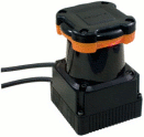
Laser Range Finder UTM-30LX from from Hokuyo
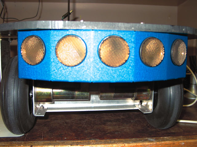
Sonar Array
Global Positioning System (GPS)
http://www.sparkfun.com/commerce/images/products/EM408-01-L_i_ma.jpg
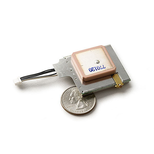
EM-408 GPS from SparkFun $64.95 each. 20 Channel EM-408 SiRF III Receiver with Antenna/MMCX
Compass
http://www.sparkfun.com/commerce/images/products/PNI-Eval-Board-Loaded_i_ma.jpg
SEN-00418 MicroMag 3-Axis Magnetometer Kit from SparkFun $239.90 each
Inertial Measurement Unit (IMU)/Vibration/Accelerometers
http://www.microstrain.com/images/product/3dm-gx2.jpg
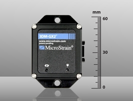
We selected 3DM-GX2 IMU from MicroStrain which is $1695.00 each. Notes for integrating the MicroStrain 3DM-GX2 IMU with the Beobot2.0 can be found here.
A more affordable option:
http://www.sparkfun.com/commerce/images/products/08454-03-L_i_ma.jpg
SEN-08454 IMU 6 Degrees of Freedom - v4 with Bluetooth from SparkFun $449.95 each.
Encoders for Odometry
These are the sensors that are furnished in Beobot2.0:
Cameras
Since we are primarily a vision robotics research group, selection of a camera (and the corresponding lens) is very critical. In addition, our system is also trying to emulate human vision. Thus, we also have to keep in mind what kind of stimulus is available to human vision system. The problem that we encounter is that a single regular camera may not be enough: 60 degree horizontal field of view, and for our 1/4” CCD camera 117cm above the ground (current Beobot2.0 configuration), cannot see the view below, i.e. what's on the ground, 4 feet and closer.
FIXXX: field of view of a single camera vs whole half hemispheric view
Just as a comparison, humans use 2 cameras (eye) with 120 degree visibility that overlaps in the middle 60 degrees. Humans also have problems seeing their feet. However, there is also temporal context (short term memory) that comes into play with the ability to move their eyes as well as bodies.
FIXXX: picture of human eyes setup
Factors
The factors to consider are listed below. Here, we believe, the most important one is the effective views that can be processed:
- View: pertains to what the robot can see from the camera at any one time.
- Resolution: in order to recognize an object in the image, we need enough details to make it up
- Latency: pertains to the time delay between when the picture is snapped and the time the image is available to be processed. We find that Firewire cameras, interfaced through a Firewire - PCI Express card (purchased from UniBrain) provides us the lowest latency.
- High dynamic range
- Auto white balance gain control.
Tasks
We also have think about what kind of tasks that we would like to give the robot:
- Object/landmark recognition. This requires rectified images so that the lines are straight.
- road recognition. The camera needs to look down low enough to see the ground.
- Gist or general scene recognition which requires a wider view, preferably 180 degrees.
Hardware Features
There are many hardware options that are available. Here the parts that can be modified are:
- Cameras: dictates latency, resolution, gain control, etc. Also make sure the available corresponding lens options include the ones that fulfill our design.
- lens: By using wider (120/180 degrees) or omni-directional lens (hemisphere), the robot can observe more of its surrounding views.
   * Distorted images; have to consider cost of image rectification processing or just deal with it.
   * Lenses can be quite costly.
- number of cameras: by simultaneously taking pictures from multiple angles, we can provide the robot with wider views. The setup can be just 2 cameras, or may requires a rig.
   * Synchronization using cable locking.
   * Undistorted images.
   * Multiple cameras are somewhat cheaper than buying specialized lens.
   * Need to consider network throughput.
   * Also, need to combine the individual image processes.
   * Still needs to expand the vertical views (to see the road).
- motorized pan/tilt: for example, servo controllers for pan-tilt control: lyxmotion. Orbit is also another option.
   * Need Pan/tilt control algorithm
   * Small view at one time: need to stitch images from different time steps.
   * Cheap options, cheaper than buying expensive lenses or multiple cameras.
   * Swiveling may induce blurring in fast movements.
Options
- Single camera with 120 degree wide angle lens or 180 degree or omni-directional fisheye lens.
- Pair of 120 degree wide angle cameras.
- 5 cameras in circular configuration spaced every 45 degrees.
- Pan/tilt cameras.
- 3D cameras about to come out around Summer 2010.
Related Notes:
- Multiple cameras is not a problem if each camera is processed locally in the computer that it connects to in Beobot2.0
- A system may use different number of cameras for training vs. testing
Laser Range Finder (LRF)
Laser Range Finder UTM-30LX from from Hokuyo
Sonar Array
Global Positioning System (GPS)
Compass
 SEN-00418 MicroMag 3-Axis Magnetometer Kit from SparkFun $239.90 each
Inertial Measurement Unit (IMU)/Vibration/Accelerometers
We selected 3DM-GX2 IMU from MicroStrain which is $1695.00 each. Notes for integrating the MicroStrain 3DM-GX2 IMU with the Beobot2.0 can be found here.
A more affordable option:
http://www.sparkfun.com/commerce/images/products/08454-03-L_i_ma.jpg
SEN-08454 IMU 6 Degrees of Freedom - v4 with Bluetooth from SparkFun $449.95 each.
Encoders for Odometry
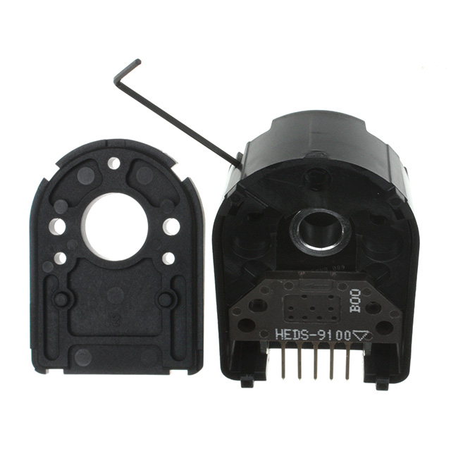 Encoder HEDM-5500#B06 from Avago Encoder . The encoder turns out to have 22:1, 22 shaft rotation to turn the wheel a single rotation.
92 miles per overflow.
Others Not Yet Selected
- Microphone
- Tactile Sensor: Bump Sensor
- Smell sensor
 Encoder HEDM-5500#B06 from Avago Encoder . The encoder turns out to have 22:1, 22 shaft rotation to turn the wheel a single rotation.
92 miles per overflow.
