Table of Contents
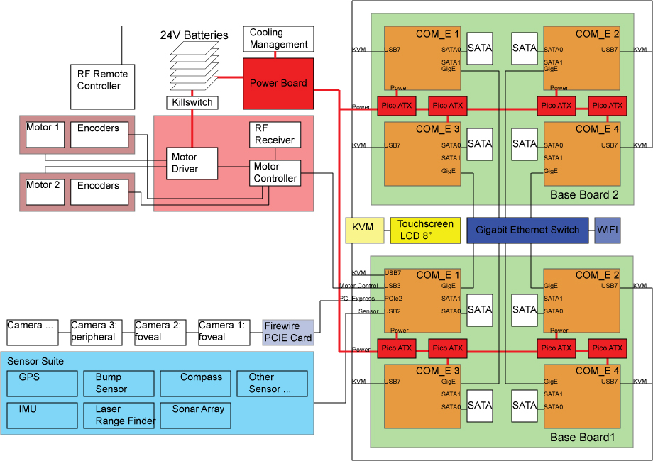
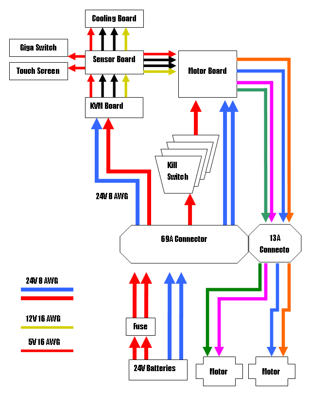
The electrical system consists of the following components: computing cluster, KVM system, power boards, sensors, motor control, and cooling system. This section also going to discuss the design decisions, part manufacturing, assembly, as well as testing.
Note that the “To Do” section is an ongoing internal message board. The public section starts at the Block Diagram section.
To Do
Block Diagram
Design And Implementation
The components in the electrical system can be divides into two types: devices that we bought (processors, sensors, LCD touch screen) and the boards to control/integrate these devices that we built from scratch:
- The boards are manufactured by Advanced Circuits.
- Most electronics components are purchased from Digikey.
- We assemble and tested most of the boards ourselves. The only ones that we needed help on are the COM Express connectors on the Base board, which are done by an outside assembly house.
There are 10 different types of board (15 total) utilized in the robot. Note that because making these boards to work properly just from the design stage is not easy, some of them has to go through more than 1 iterations to iron out all the electrical problems.
The implementation and testing of these boards are described within its sub-systems below.
Below is the cost accrued in manufacturing, populating, and assembling the boards. Note there are “starting costs” that we did not include such as:
- Altium software: $5000. However, since we provide all the Altium and Gerber files, there is no need to have one unless you would like to modify them.
- Soldering irons
- heat shrinks for connectors
- Tools such as cutters, crimpers, etc.
Altium Files
Here is the BEOBOT2.0 ZIP FILE of all the Altium project, Gerber files and Bill of Materials (BOM).
We have different Altium projects for the different boards, most are in their own individual folder. In addition, some boards have multiple folders for past prototypes.
Here are the active folders:
- Baseboard: B2 PrototypeFinal; Project file: Beobot2_PrototypeFinal.PrjPcb
- Keyboard Video Mouse (KVM) board: KVM PrototypeFinal; Project file: Beobot2_KVM_PrototypeFinal.PrjPcb
- Breakout Board: BreakoutBoard Prototype2; Project file: Beobot2_Prototype2_BreakoutBoard.PrjPcb
- Back Main Board: PanelMountBackBoard Prototype2; Project file: Beobot2_Prototype2_PanelMountBackBoard.PrjPcb
- Display Board: PanelMountDisplayBoard Prototype2; Project file: Beobot2_Prototype2_PanelMountDisplayBoard.PrjPcb
- USB8 Adapter Board: PanelMountBackBoard Prototype2; Project file: Beobot2_Prototype2_USB8Adapter.PrjPcb
- USB4 Adapter Board: PanelMountBackBoard Prototype2; Project file: Beobot2_Prototype2_USB4Adapter.PrjPcb
- Sensor Board: SensorBoard Prototype2; Project file: Beobot2_Prototype2_SensorBoard.PrjPcb
- Motor Control Board: MotorBoard Prototype2; Project file: Beobot2_Prototype2_MotorBoard.PrjPcb
- Cooling Control Board: CoolingBoard Prototype2; Project file: Beobot2_Prototype2_CoolingBoard.PrjPcb
- PropStick: PropBoard Prototype2; Project file: PropBoard.PrjPcb
Electronic Boards Related Cost
| Number | Item | Purpose | Cost | Count | Item Total | Supplier | Notes |
|---|---|---|---|---|---|---|---|
| 1 | Board Manufacturing | For all boards | $620.39 | 1 | $620.39 | Advanced Circuits | Student discounts, combine boards to reduce price |
| 2 | Electronic Components | Various (see FIXXX for BOM) | $7185.85 | 1 | $7185.85 | Digikey | minus the connectors itemized in subsections below |
| 3 | [Electronics component assembly | for the .5mm pitch COM Express connector | $250 | 1 | $250 | Assembly House Incorporated |
Total electronics cost: $8056.24 NOTE: prices may change and shipping cost not included.
Electrical Sub-systems
The electrical sub-systems are listed below and the cost for each is itemized below. Note that the electronic board implementation cost is bundled together and not included in the individual sub-systems.
| Number | Sub-sytem | Cost | Notes |
|---|---|---|---|
| 1 | Electronics | $8056.24 | |
| 2 | Computing Cluster | $7779.09 | |
| 3 | KVM | $327.95 | |
| 4 | Input/Output | $46.8 | |
| 5 | Power | $777.20 | |
| 6 | Sensors | $2666.33 | |
| 7 | Motor Control | $605.99 | |
| 8 | Cooling | $17 |
Total electrical system cost: $20276.6 NOTE: prices may change and shipping cost not included.
Computing Clusters
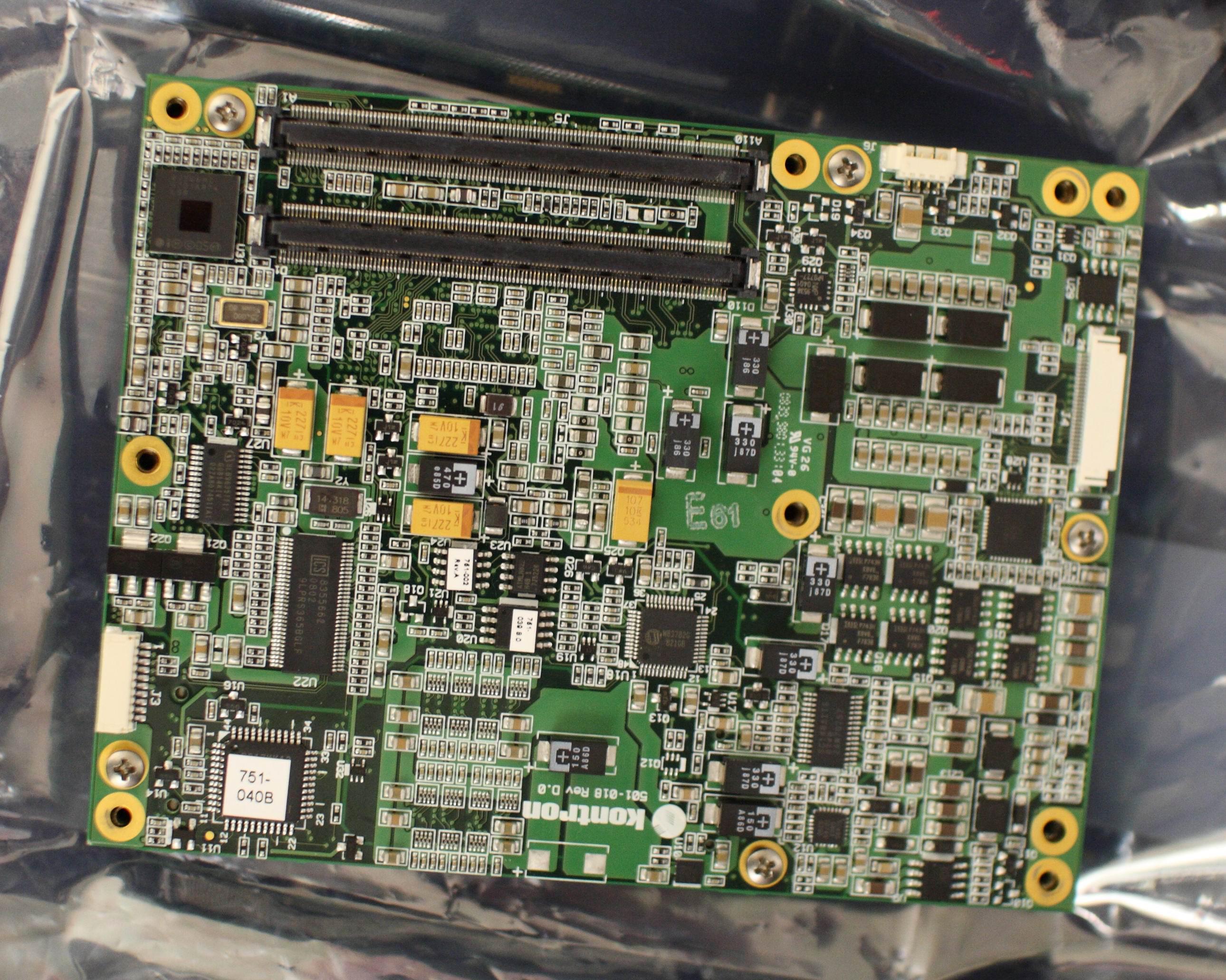
We use COM-EXPRESS for the basic processors.
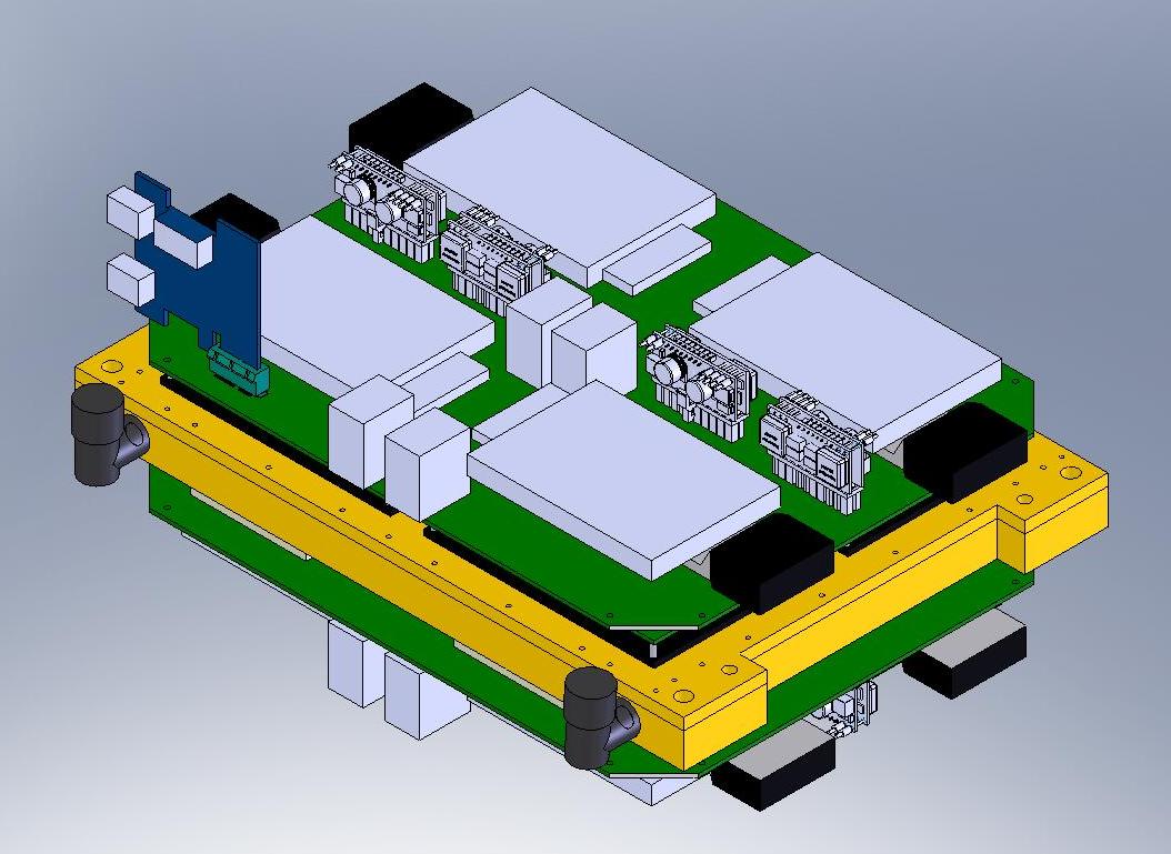
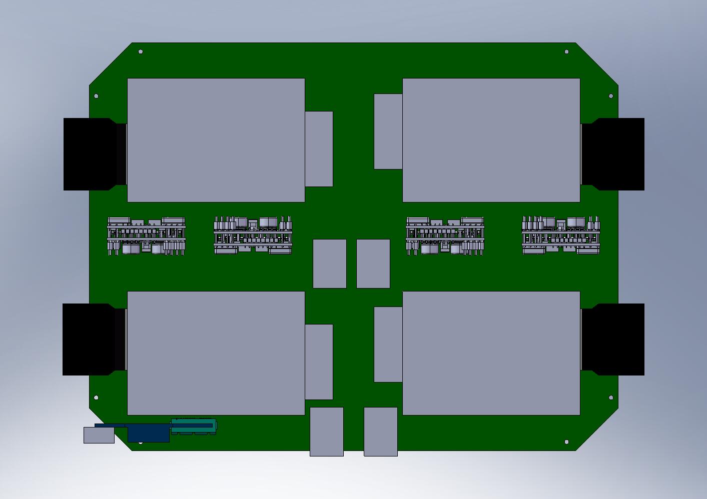
There are 8 of them and they are placed on 1 of two baseboards that sandwiches a water-cooling block on the image below. These baseboards, which is manufactured by Advanced Circuits break out signals in and out of the processors to all peripheral connectors/sensors.
We use a Gigabit Ethernet switch to facilitate communication between the processors. We also connect a FIXXX WiFi bridge for wireless connection to the outside computers.
Purchased Components
The following table itemize the components that are used in this sub-system:
| Number | Item | Purpose | Cost | Count | Item Total | Supplier | Notes |
|---|---|---|---|---|---|---|---|
| 1 | Kontron ETXexpress-MC | COM Express Module | $708 | 8 | $5664 | WDL systems | Only Kontron Supplier in US |
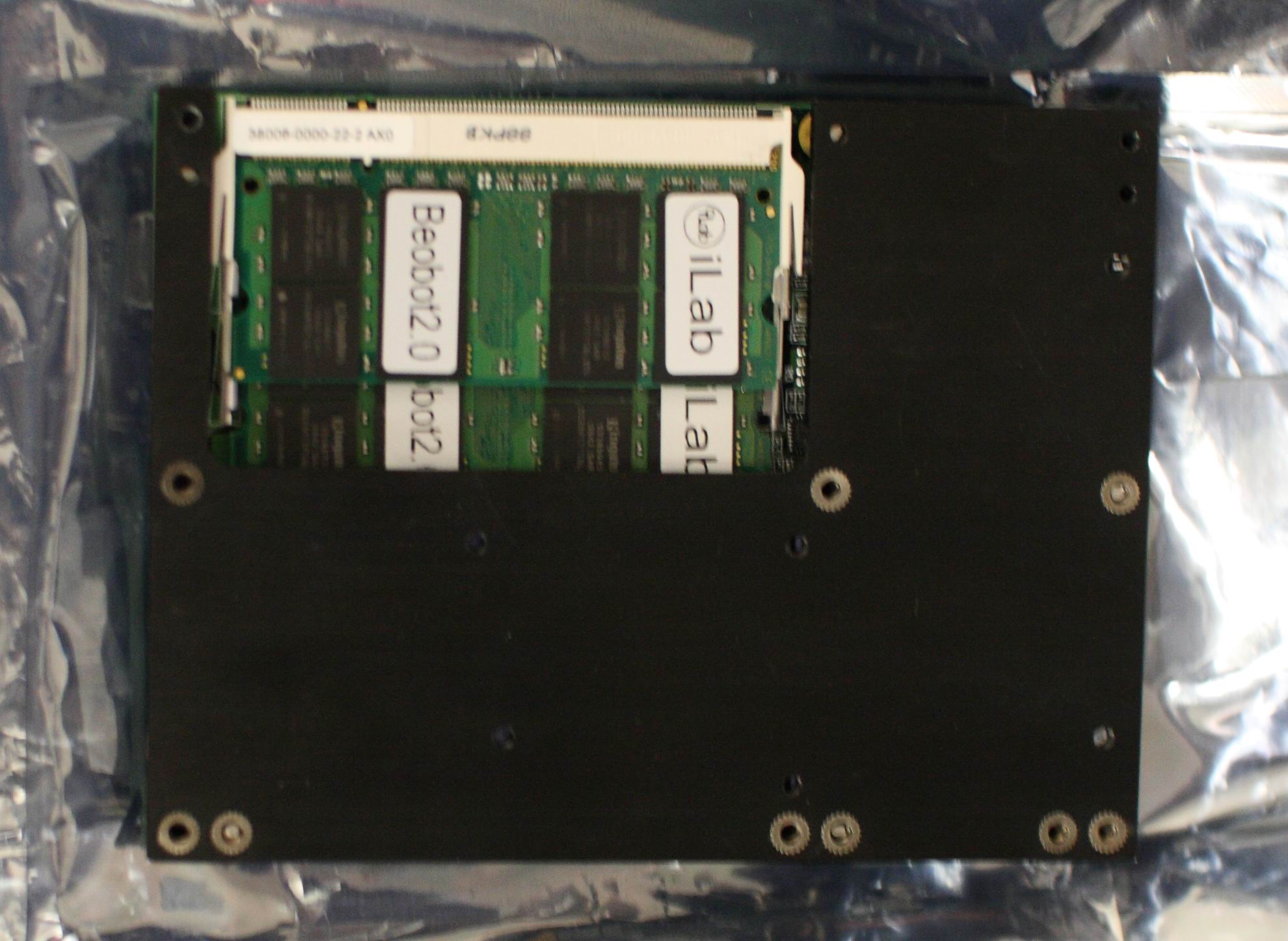
| 2 | Heatspreader for ETXexpress-MC | threaded hole heat spreader | $24 | 8 | $192 | WDL systems | |
| 3 | Memory | two 2GB SO-DIMM Memory per computer | $27.99 | 16 | $447.84 | Newegg | |
| 4 | Solid State Hard Drive | 64GB SATA SSD HD | $138 | 8 | $1104 | Newegg | |
| 5 | Gigabit Ethernet Switch | NETGEAR GS116 | $162.99 | 1 | $162.99 | Newegg | |
| 6 | Gigabit Ethernet Cables | Cat 6 for Gigabit Ethernet | $.69 | 12 | $8.28 | Newegg | |
| 7 | WiFi Access Point | TRENDnet TEW 453APB | $99.99 | 2 | $199.98 | Newegg |
Total sub-system cost: $7779.09 NOTE: prices may change and shipping cost not included.
Boards
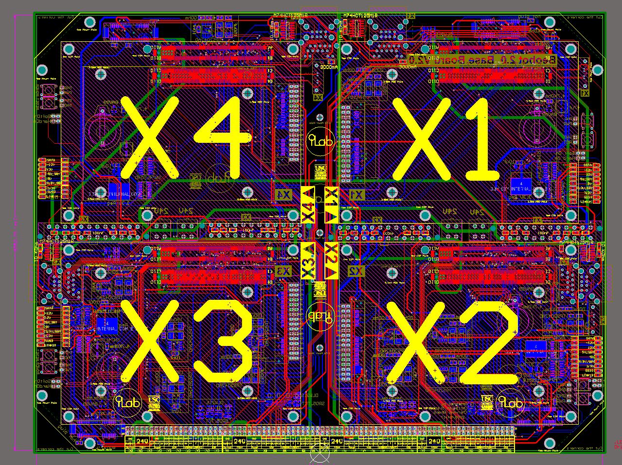
We use 2 Carrier/base Boards with each board accommodating 4 COM Express modules. The PCB Files and the component Bill of Materials (BOM) are available at the Altium Files section above.
| Board Name | Altium Layout | 3D Model | Files | Notes |
|---|---|---|---|---|
| Base Board/Carrier Board |
 |
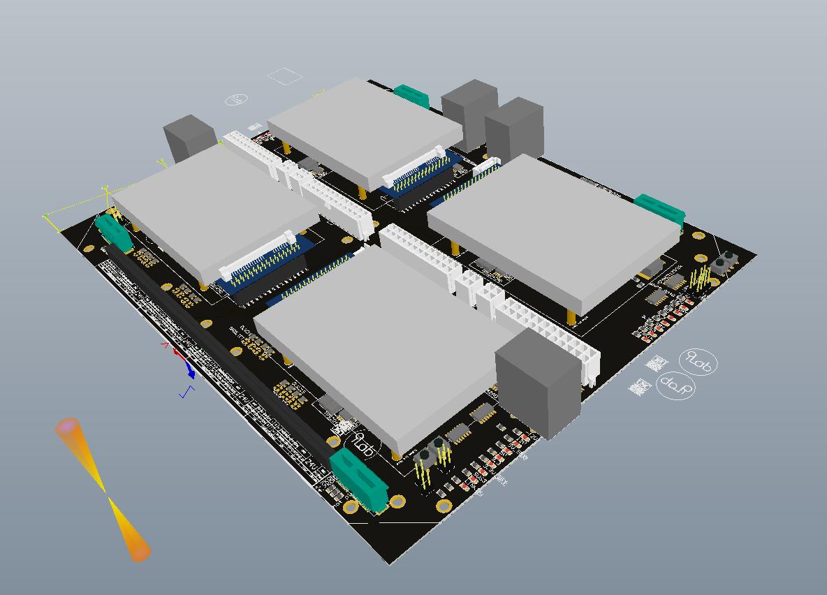 |
Both are at the center of the robot. SOLIDWORKS: The assembly name is: base_board2.SLDASM. Location: robot7 → robot_computer7 → computer_system7 → processors_block7 → base_board2. ALTIUM: The project file is “B2 PrototypeFinal/Beobot2_PrototypeFinal.PrjPcb”. | This is by far the hardest board to implement and there are 3 prototypes: Prototype 1,Prototype 1.1, and Final prototype. |
Keyboard Mouse Monitor (KVM) system Display Devices
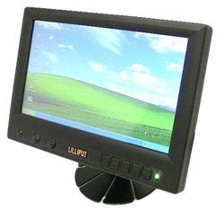
The KVM system allows the user to access each of the 8 individual COM Express module. The KVM switch is 8 input : 2 output, with the output being either a regular monitor (and keyboard and mouse), or an 8” LCD Touch Screen Lilliput 8” Widescreen (16:9) VGA Touchscreen.
Related information:
Purchased Components
The following table itemize the components that are used in this sub-system:
| Number | Item | Purpose | Cost | Count | Item Total | Supplier | Notes |
|---|---|---|---|---|---|---|---|
| 1 | LCD touchscreen | 889GL-80NP/C/T | $268 | 1 | $268 | Mp3Car | |
| 2 | camera post | Compact Ballhead with Rapid Connect System | $59.95 | 1 | $59.95 | B&H Photo Video |
Total sub-system cost: $327.95 NOTE: prices may change and shipping cost not included.
Boards
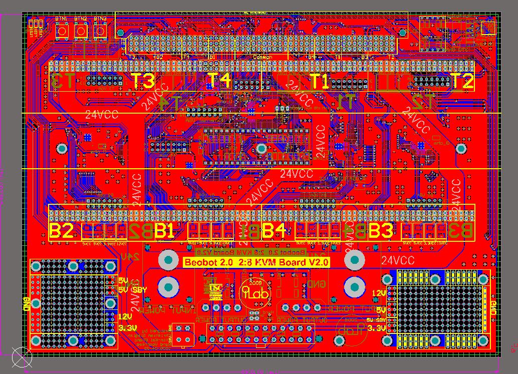
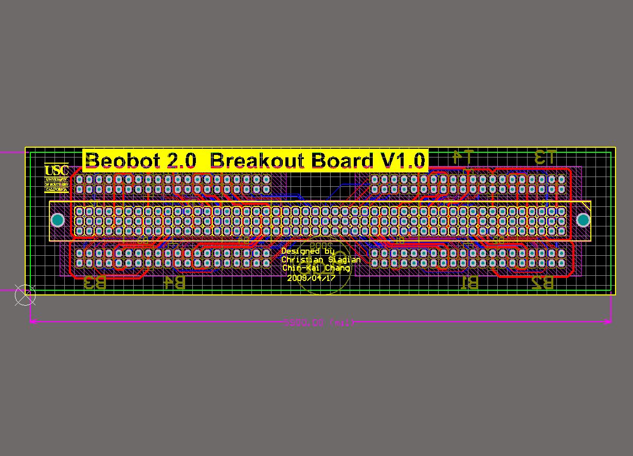
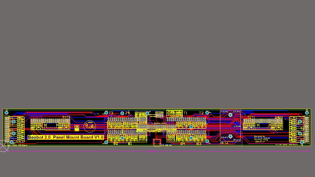
We have the following boards to connect from the computing cluster to the panel mount KVM (VGA and 2 USB) connectors. The PCB Files and the component Bill of Materials (BOM) are available at the Altium Files section above.
| Board Name | Altium Layout | 3D Model | Files | Notes |
|---|---|---|---|---|
| Keyboard Video Mouse (KVM) board |
 |
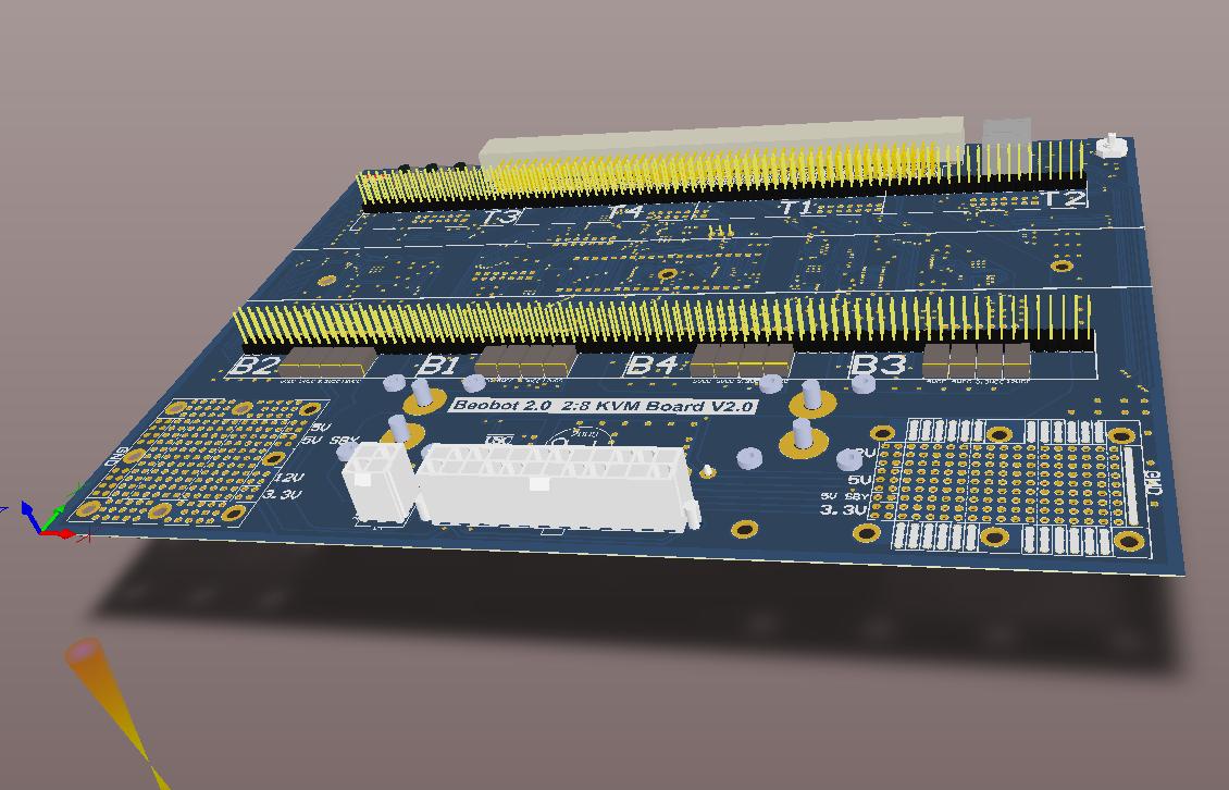 |
This board is behind the two baseboards. SOLIDWORKS: The assembly name is: side_board6.SLDPRT. Location: robot7 → robot_computer7 → computer_system7 → side_board7 → side_board6. ALTIUM: The project file is “KVM PrototypeFinal/Beobot2_KVM_PrototypeFinal.PrjPcb”. | This board to access individual COM Express modules. It is also the entry point for the 24V power from the battery. We have 48 (6 per computer) pins for them to flow to the base board. There are 2 prototypes: KVM, final KVM board. Note that we use a Propeller microcontroller (that we package in a DIP40 footprint PropStick) to control the KVM USB and VGA. |
| Breakout Board |
 |
 |
The board would be hanging on top of the KVM board. SOLIDWORKS: not modeled. ALTIUM: The project file is “BreakoutBoard Prototype2/Beobot2_Prototype2_BreakoutBoard.PrjPcb”. | This board allows us to use a high density board-to-board connector to connect the inside computing module to the peripheral panel mount connectors/devices. Here we use a 150-pin (3 rows x 50pins) tyco connector. There is 1 prototype: final Breakout board |
| Back Main Board |
 |
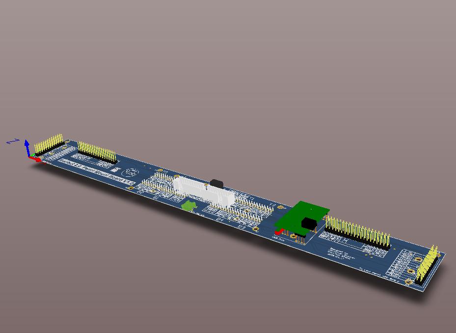 |
Ath the back top of the robot. SOLIDWORKS: The assembly name is: Robot_back_panel_mount_board.SLDPRT. Location: robot7 → robot_computer7 → robot_computer_case7 → Robot_back_panel_mount_board. ALTIUM: The project file is “PanelMountBackBoard Prototype2/Beobot2_Prototype2_PanelMountBackBoard.PrjPcb”. | This board houses the panel mount USB as well as the KVM connectors. It has a USB hub to split a single USB KVM signal for the Keyboard, Mouse, and USB touchscreen lanes. There is 1 prototype: final back main board |
| Display Board |
 |
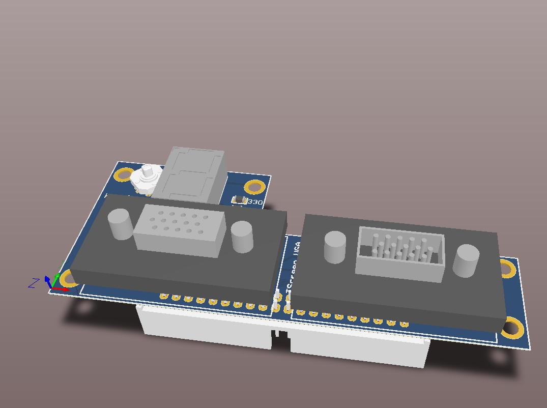 |
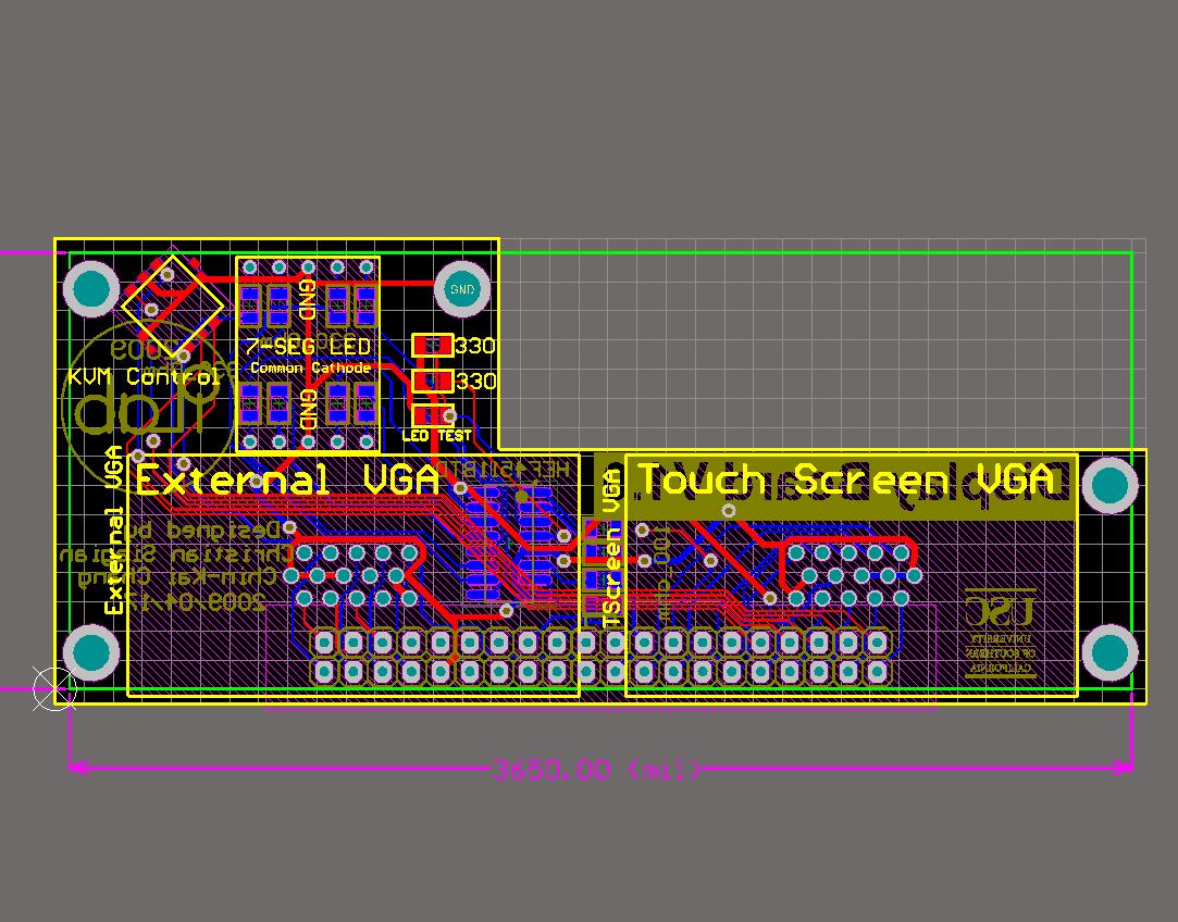
At the back top of the robot. SOLIDWORKS: The assembly name is: panel_mount_display_board.SLDPRT. Location: robot7 → robot_computer7 → robot_computer_case7 → robot_topcenterback_connector_system → panel_mount_display_board. ALTIUM: The project file is “PanelMountDisplayBoard Prototype2/Beobot2_Prototype2_PanelMountDisplayBoard.PrjPcb”. | This board has VGA and KVM related module. It has a seven-segment display and a switch to toggle between computers. There is 1 prototype: final display board |
Input/Output Interface
The input and output connections to outside devices (sensors, for example) are done through various panel mount connectors. The traces goes through the same boards as the KVM system (Keyboard Video Mouse (KVM) board , Breakout Board, Back Main Board, and Display Board), plus a few extension cable some of which we have to create ourselves (check below). With these extra connectors we can add additional device such as speakers (through USB audio dongle), for example.
Purchased Components
The following table itemize the components that are used in this sub-system:
| Number | Item | Purpose | Cost | Count | Item Total | Supplier | Notes |
|---|---|---|---|---|---|---|---|
| 1 | 6" FireWire panel mount connector cable | connection from firewire card to panel mount connector | $23.1 | 1 | $23.1 | USBfirewire.com | |
| 2 | 24" FireWire cable | panel mount connector to camera | $23.7 | 1 | $23.7 | USBfirewire.com |
Total sub-system cost: $46.8 NOTE: prices may change and shipping cost not included.
Boards
We have 2 types of USB extension panel mount cables that has an adapter board to utilize the connectors. The PCB Files and the component Bill of Materials (BOM) are available at the Altium Files section above.
| Board Name | Altium Layout | 3D Model | Files | Notes |
|---|---|---|---|---|
| USB8 Adapter Board |
 |
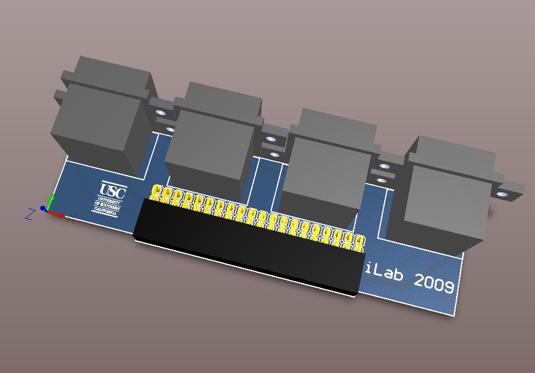 |
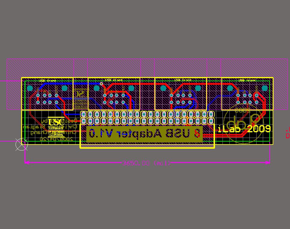
Would be at the side top of the robot. SOLIDWORKS: Not modeled. ALTIUM: The project file is “PanelMountBackBoard Prototype2/Beobot2_Prototype2_USB8Adapter.PrjPcb”. | This is a small USB adapter for 8 panel mount outlets. There is 1 prototype: final USB8 board |
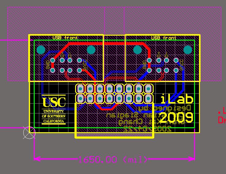
| USB4 Adapter Board |
 |
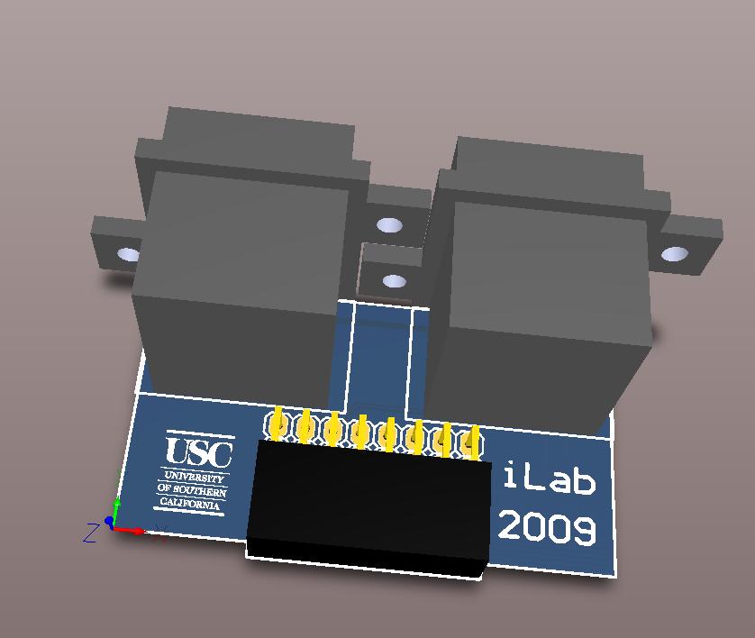 |
Would be at the side top of the robot. SOLIDWORKS: Not modeled. ALTIUM: The project is “PanelMountBackBoard Prototype2/Beobot2_Prototype2_USB4Adapter.PrjPcb”. | This is a small USB adapter for 4 panel mount outlet. There is 1 prototype: final USB4 board |
Power System
Power is regulated by 9 PICO-ATX modules. The power supply itself is provided by the two 12V 35Ah wheelchair' batteries, connected in series. We use 8 separate PICO-ATX module to provide power to each COM Express module. There is an extra PICO-ATX for powering all connected peripheral (sensors, Motor, cooling) boards.
Purchased Components
The following table itemize the components that are used in this sub-system:
| Number | Item | Purpose | Cost | Count | Item Total | Supplier | Notes |
|---|---|---|---|---|---|---|---|
| 1 | PICO ATX PSU | 12-32V input DC-DC ATX power supply unit (PSU) | $55.5 | 10 | $555 | miniBox | Almost 10% discount when buying 10 to 49 ($15 for the 10th module) |
| 2 | Fuses | 40-amp AFS Fuses | $9.99 | 1 | $9.99 | Crutchfield | |
| 3 | Fuse Holder | AFS Fuse Holder 8-ga. | $24.99 | 1 | $24.99 | Crutchfield | |
| 4 | Ground Cable | per ft 8 ga. Blue Power Cable | $1.25 | 10 | $12.5 | Crutchfield | |
| 5 | Power Cable | per ft 8 ga. Red Power Cable | $1.25 | 10 | $12.5 | Crutchfield | |
| 6 | Battery Power Connector (recpt) | CONN RECEPT PNL MT 4POS SIZE 8 | $34.59 | 1 | $34.59 | Digikey | |
| 7 | Battery Power Connector (plug) | CONN PLUG FREE/HANG 4POS SIZE 8 | $56.67 | 1 | $56.67 | Digikey | |
| 8 | KVM Power Connector (recpt) | CONN PLUG RADSOK 2POS | $15.4 | 2 | $30.8 | Digikey | |
| 9 | KVM Power Connector (plug) | CONN RECEPT PIN RADSOK 2POS PCB | $14.1 | 2 | $28.2 | Digikey | |
| 14 | Killswitch | Emergency E-Stop Switch w/ LED | $2.99 | 4 | $11.96 | Cebtenary | Import from Taiwan |
Total sub-system cost: $777.20 NOTE: prices may change and shipping cost not included.
Boards
The Power traces goes through the KVM and base boards.
Sensors
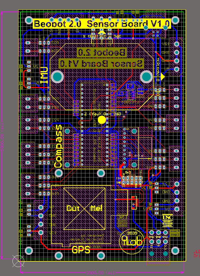
We have the following sensors, some of which (GPS, Compass, IMU) are integrated through the sensor board :
- Cameras: we use Firewire (over PCI Express), but we may also use Internet Protocol (IP) cameras using the Gigabit ethernet.
- Laser Range Finder
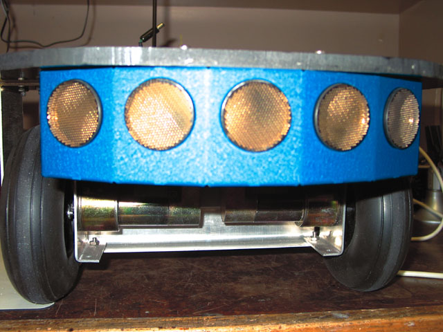
- Sonar Array
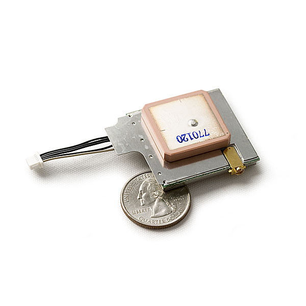
- Global Positioning System (GPS)
- Compass
- Inertial Measurement Unit (IMU)
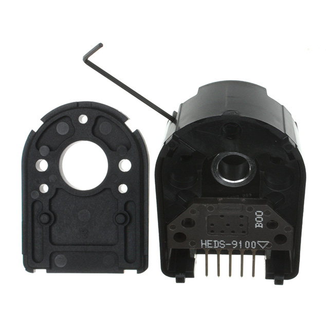
- Encoders
Purchased Components
The following table itemize the components that are used in this sub-system:
| Number | Item | Purpose | Cost | Count | Item Total | Supplier | Notes |
|---|---|---|---|---|---|---|---|
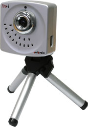
| 1 | Firewire camera | UniBrain FireI Camera | $109 | 1 | $109 | UniBrain | |
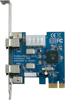
| 2 | FireWire Card | PCI Express - Firewire card | $49 | 1 | $49 | UniBrain | |
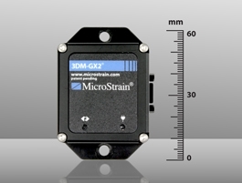
| 3 | IMU | 3DM-GX2 Inertial Measurement Unit | $1695 | 1 | $1695 | MicroStrain | |
| 4 | Compass | MicroMag 3-Axis Magnetometer | $239.9 | 1 | $239.9 | SparkFun | |
| 5 | GPS | 20 Channel EM-408 SiRF III Receiver with Antenna/MMCX | $64.95 | 1 | $64.95 | SparkFun | |
| 6 | Sonar | SensComp Mini S sonar | $68.50 | 7 | $68.50 | SensComp | |
| 7 | USB Hub | In case there is a need to add more USB connection | $7.99 | 2 | $15.98 | Newegg | |
| 8 | 24" USB cable | 24” right angle USB (connect sensor board with cluster) | $13 | 1 | $13 | USBfirewire.com |
Total sub-system cost: $2666.33 NOTE: prices may change and shipping cost not included.
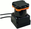
Also note that our Laser Range Finder is donated by Hokuyo AUT and thus not part of the total. We categorize this device as optional because we include the cost of the sonar suite. The Hokuyo Laser range finder can be found here and the cost ranges from $1300 to $5600.
Boards
The PCB Files and the component Bill of Materials (BOM) are available at the Altium Files section above.
| Board Name | Altium Layout | 3D Model | Files | Notes |
|---|---|---|---|---|
| Sensor Board |
 |
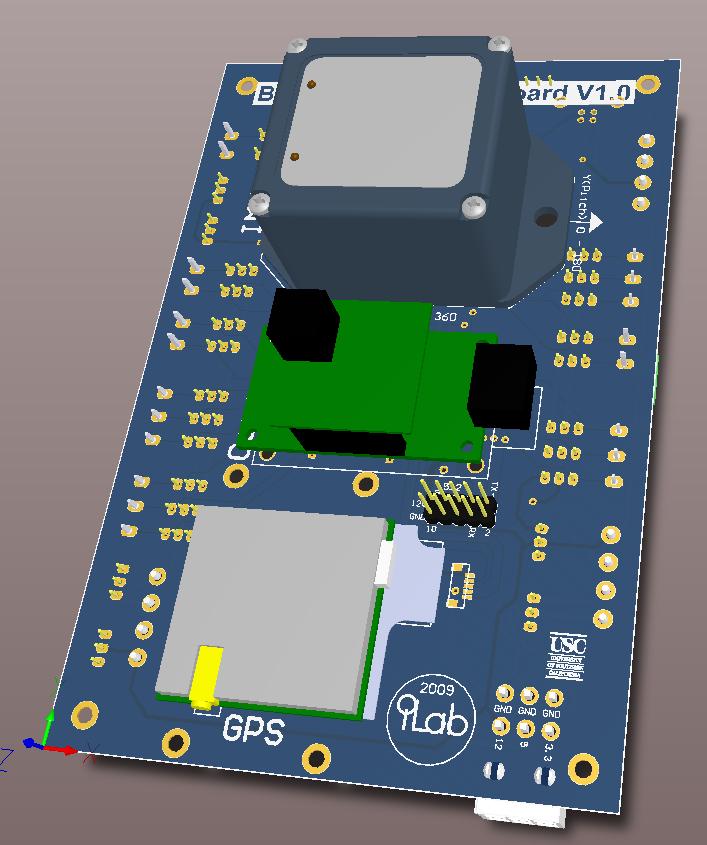 |
The board is at the back of the robot. SOLIDWORKS: The assembly name is: sensor_system7.SLDASM. Location: robot7 → robot_computer7 → robot_computer_case7 → sensor_system7. ALTIUM: The project file is “SensorBoard Prototype2/Beobot2_Prototype2_SensorBoard.PrjPcb”. | The Sensor Board manages sensors such as GPS, IMU, and Compass. It also has a few open pins for expansion. There is 1 prototype: P1 Sensor board. Note that we use a Propeller microcontroller (that we package in a DIP40 footprint PropStick) to format some of the serial data from sensors. |
Motor Control
This system pertains to the robot control movement. There are a few control sources: computing cluster (autonomous mode), various direct uninterrupted devices (sonar, killswitches, cliff sensors), and RC remote controller (for manual mode).
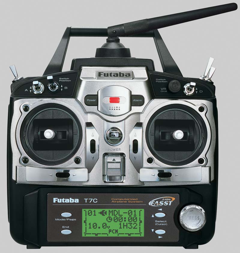
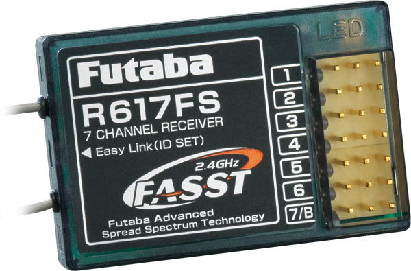
In order to have a more robust system, we use the latest 2.4Ghz RC control system from Futaba, which have more bandwidth and much less interference compare with the 33Mhz RC system. Also, killswitches are placed all over the robot for last resort safety mechanisms.
To provide the motors with power we used Dimension Engineering Sabertooth dual 25A motor drivers.
We also modified the motors to add encoders. We splice a USB cable to connect the encoder to the Motor Connector on the robot body. Note that the encoder model is not integrated with the rest of the robot (robot7.SLDASM).
Purchased Components
The following table itemize the components that are used in this sub-system:
| Number | Item | Purpose | Cost | Count | Item Total | Supplier | Notes |
|---|---|---|---|---|---|---|---|
| 1 | Radio Controller | Futaba-7C 7-Channel 2.4GHz System | $279.99 | 1 | $279.99 | Futaba RC | |
| 2 | Motor Driver | SaberTooth 2×25 Motor Driver | $124.99 | 1 | $124.99 | Dimension Engineering | |
| 3 | 24" USB cable | 24” left angle USB (connect motor board with cluster) | $12.5 | 1 | $12.5 | USBfirewire.com | |
| 4 | Motor connector (recept) | CONN RECEPT 12POS W/SOCKT SOLDER | $25.91 | 1 | $25.91 | Digikey | |
| 5 | Motor connector (plug) | CONN PLUG 12POS W/PINS SOLDER | $24.27 | 1 | $24.27 | Digikey | |
| 6 | Motor power cable | Monster 14 AWG 4C Speaker Cable 1 ft. CL3 | $1.45 | 25 | $36.25 | PartsExpress | |
| 7 | Encoders | OPT 2CH QUICK ASSM | $51.04 | 2 | $102.08 | Digikey |
Total sub-system cost: $605.99 NOTE: prices may change and shipping cost not included.
Boards
The PCB Files and the component Bill of Materials (BOM) are available at the Altium Files section above.
| Board Name | Altium Layout | 3D Model | Files | Notes |
|---|---|---|---|---|
| Motor Control Board |
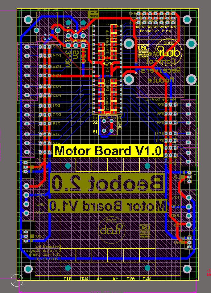 |
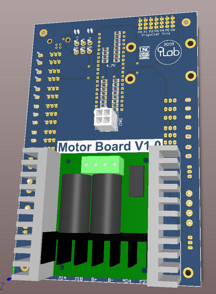 |
At the back of the robot. SOLIDWORKS: The assembly name is: motor_system7.SLDASM. Location: robot7 → robot_computer7 → robot_computer_case7 → motor_system7. ALTIUM: The project file is “MotorBoard Prototype2/Beobot2_Prototype2_MotorBoard.PrjPcb”. | The Motor Control board house the motor driver and RF remote control receiver. It also has a few open pins for sensor expansion. There is 1 prototype: P1 motor board. Note that we use a Propeller microcontroller (that we package in a DIP40 footprint PropStick) to control the motor inputs (either from the RC or the cluster). |
Cooling System
We have a board to control the water-cooling system. It provides power to:
- water pump
- two fans cooling the radiator.
It takes monitoring data from:
- flow Meter
- liquid temperature sensor.
We also have a propeller chip to process sonar array data because of its close proximity to the array (to minimize cables). In addition, we have a few extra open pins for sensor expansion.
Purchased Components
Most items are listed in the mechanical portion of the Water Cooling system except for a USB cable to connect the cooling control board to the cluster:
| Number | Item | Purpose | Cost | Count | Item Total | Supplier | Notes |
|---|---|---|---|---|---|---|---|
| 1 | USB cable | 16” double angle USB (connect cooling board with cluster) | $17 | 1 | $17 | USBfirewire.com |
Total sub-system cost: $17 NOTE: prices may change and shipping cost not included.
Boards
The PCB Files and the component Bill of Materials (BOM) are available at the Altium Files section above.
| Board Name | Altium Layout | 3D Model | Files | Notes |
|---|---|---|---|---|
| Cooling Control Board |
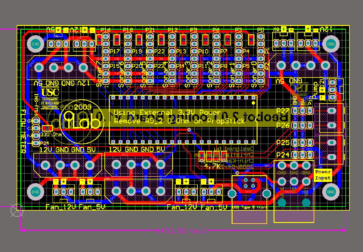 |
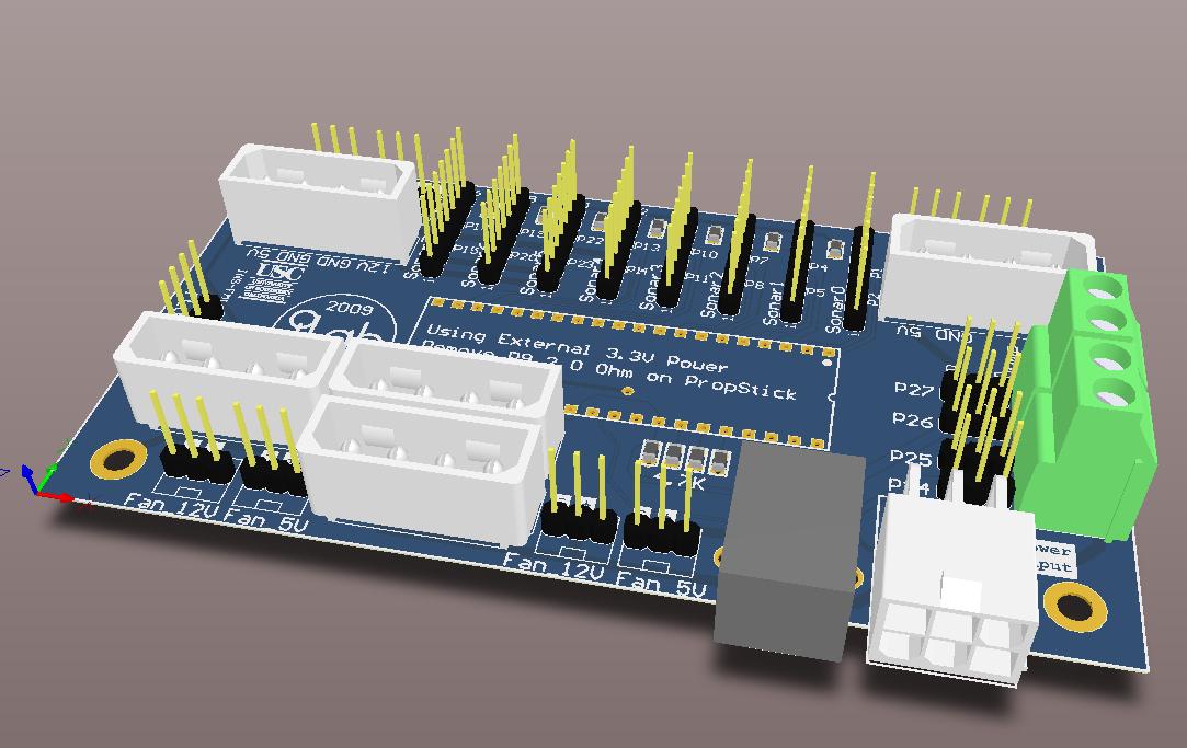 |
At the front top of the robot. SOLIDWORKS: The assembly name is: cooling_control.SLDASM. Location: robot7 → robot_computer7 → computer_system7 → cooling_system7 → cooing_control. ALTIUM: The project file is “CoolingBoard Prototype2/Beobot2_Prototype2_CoolingBoard.PrjPcb”. | There is 1 prototype: P1 cooling board. Note that we use a Propeller microcontroller (that we package in a DIP40 footprint PropStick) to process sonar as well as flowmeter data. |
Back to Beobot 2.0
